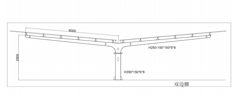
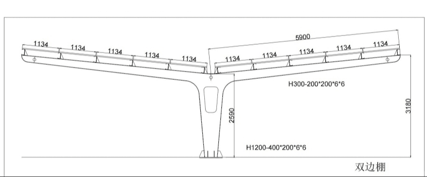
2 × 6,000 mm · charger rail
60002900H350×150×6×8H250-150×150×6×8
Standard double-side frame; charger brackets and tray are added to this geometry.

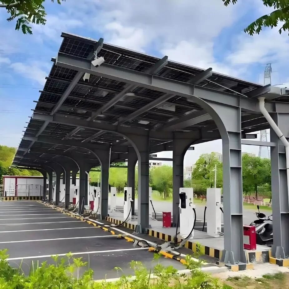 Project photograph
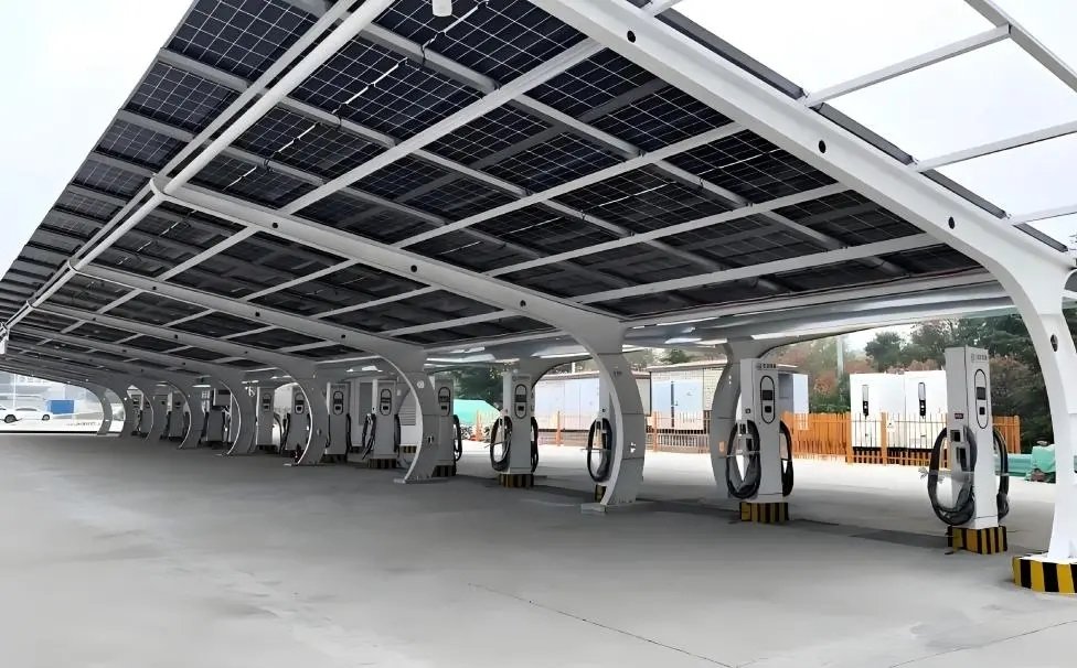
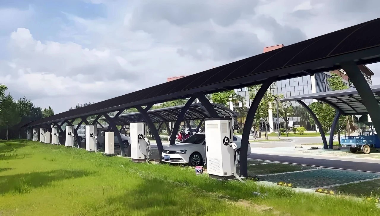
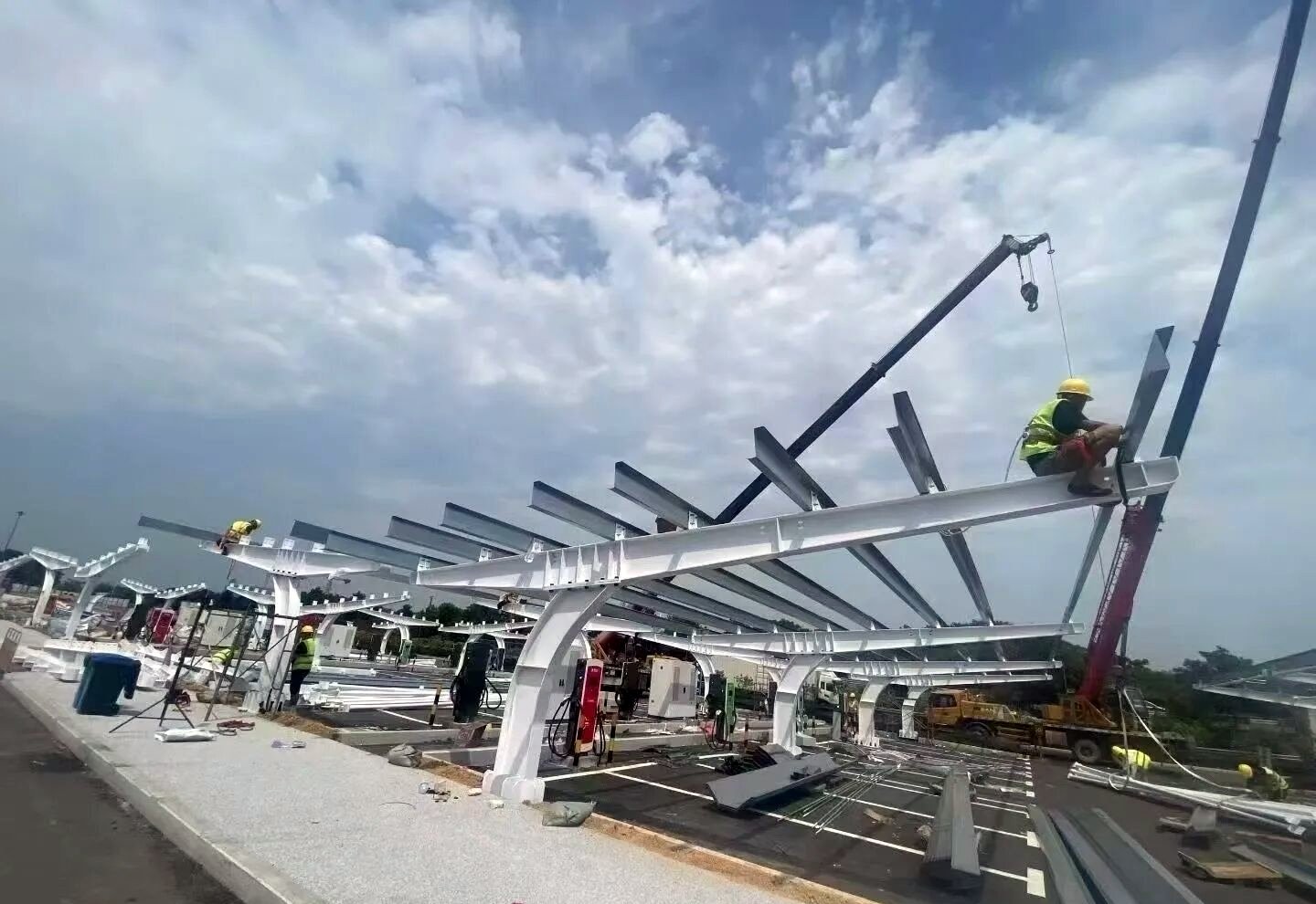
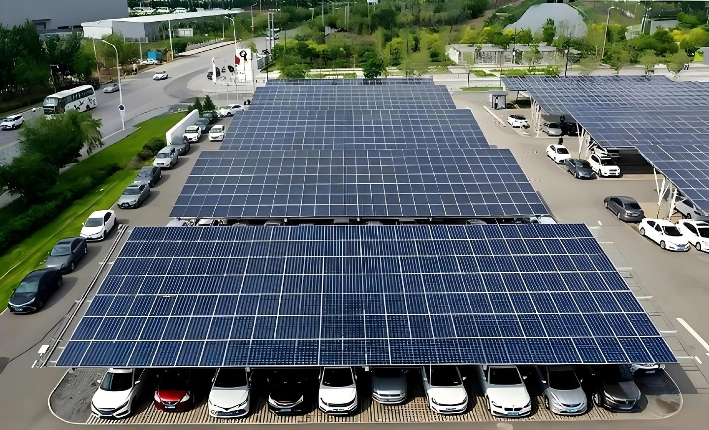
A carport frame prepared for chargers, cable tray, metering and future load growth.
Photographs from delivered projects. Dimensions are confirmed on the approved drawing before fabrication.
Brackets positioned from the charger template, not on site.
Galvanised tray and conduit run under the purlins to the column riser.
Room reserved for isolation, metering and future load growth.
Bollards, wheel stops and signage coordinated with the layout.
The EV charging carport is the standard carport frame with the electrical interface designed in from the start. Charger brackets are welded or bolted at the column, a galvanised cable tray runs under the purlins, and a riser brings the supply up the column to the agreed meter position.
Layout follows the charger datasheet: the mounting height, service clearance and cable radius are checked before fabrication, so the installer is not drilling on site. The structure itself remains a hot-dip galvanised H-beam frame with the same base plate and foundation options as the other carports.
It is used for workplace and retail charging, fleet depots and public parking where the charger count is expected to grow.
| Bays | 2–12 per row |
|---|---|
| Charger rail | Welded or bolted bracket |
| Cable tray | Galvanised, integrated |
| Structure | H-beam, hot-dip galvanised |
| Foundation | Concrete base or ground screw |
| Finish | Galvanised or powder coated |
| Charger spacing | Set to the charger datasheet |
| Safety | Bollards and wheel stops optional |
| Metering | Space reserved at the column |
| Design load | Set to local wind and snow load |
Final specification is confirmed on the drawing and against the approved sample.
Photographs from carport projects — structure, underside detail and the finished parking rows.
All dimensions in millimetres. Sections are engineered to the project wind and snow load; the approved drawing governs fabrication.
Standard double-side frame; charger brackets and tray are added to this geometry.
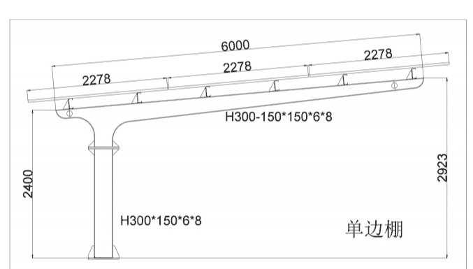
Single-side charging row with the charger post at the column line.
Long-span charging row for wide bays and high-clearance vehicles.
3D concepts used during layout discussion. Geometry, sections and finish are confirmed on the approved GA drawing.
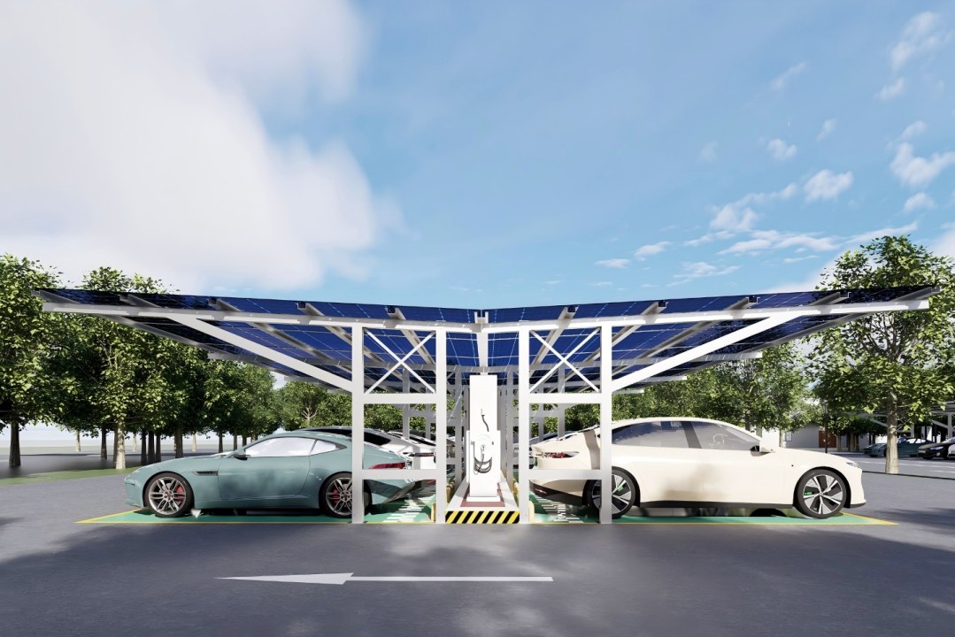
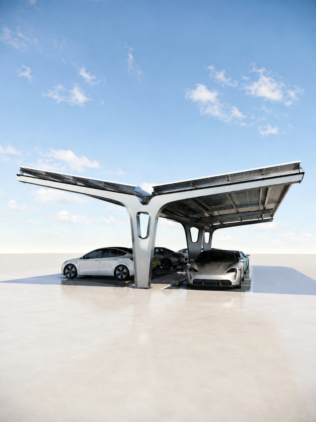
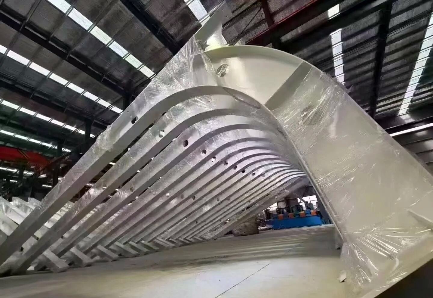
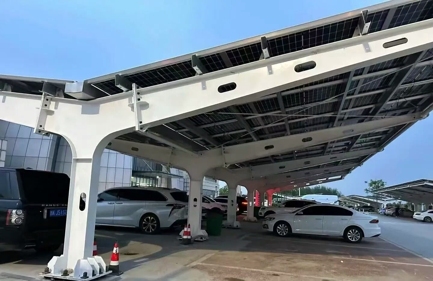
The frame is erected and plumbed before the electrical contractor starts. Cable tray, conduit and the column riser are already in place, so charger mounting is a bolt-on operation against a prepared bracket rather than a site fabrication.
The frame, finish and electrical interface are set before fabrication — not adjusted on site.
AC or DC chargers from the client's preferred brand; bracket drilled to the template.
Tray under the purlins, conduit down the column to the meter or feeder pillar.
Space reserved for isolation, metering and a future feeder.
Bollards, wheel stops and column guards for charging bays.
LED luminaires under the canopy with a photocell or timer option.
Bay marking, charger instructions and fascia branding.
The bracket is made to the charger template, so most AC and DC brands can be accommodated. Send the datasheet with the order and the mounting detail is drawn before fabrication.
Yes, a galvanised tray and conduit route can be integrated into the frame, with a riser at the agreed column.
The carport supplier provides the structure, tray, conduit and mounting points; the electrical installation and connection are carried out by the local contractor to local code.
Yes. The frame can be prepared with tray, conduit and a spare riser so chargers can be added without drilling the structure.
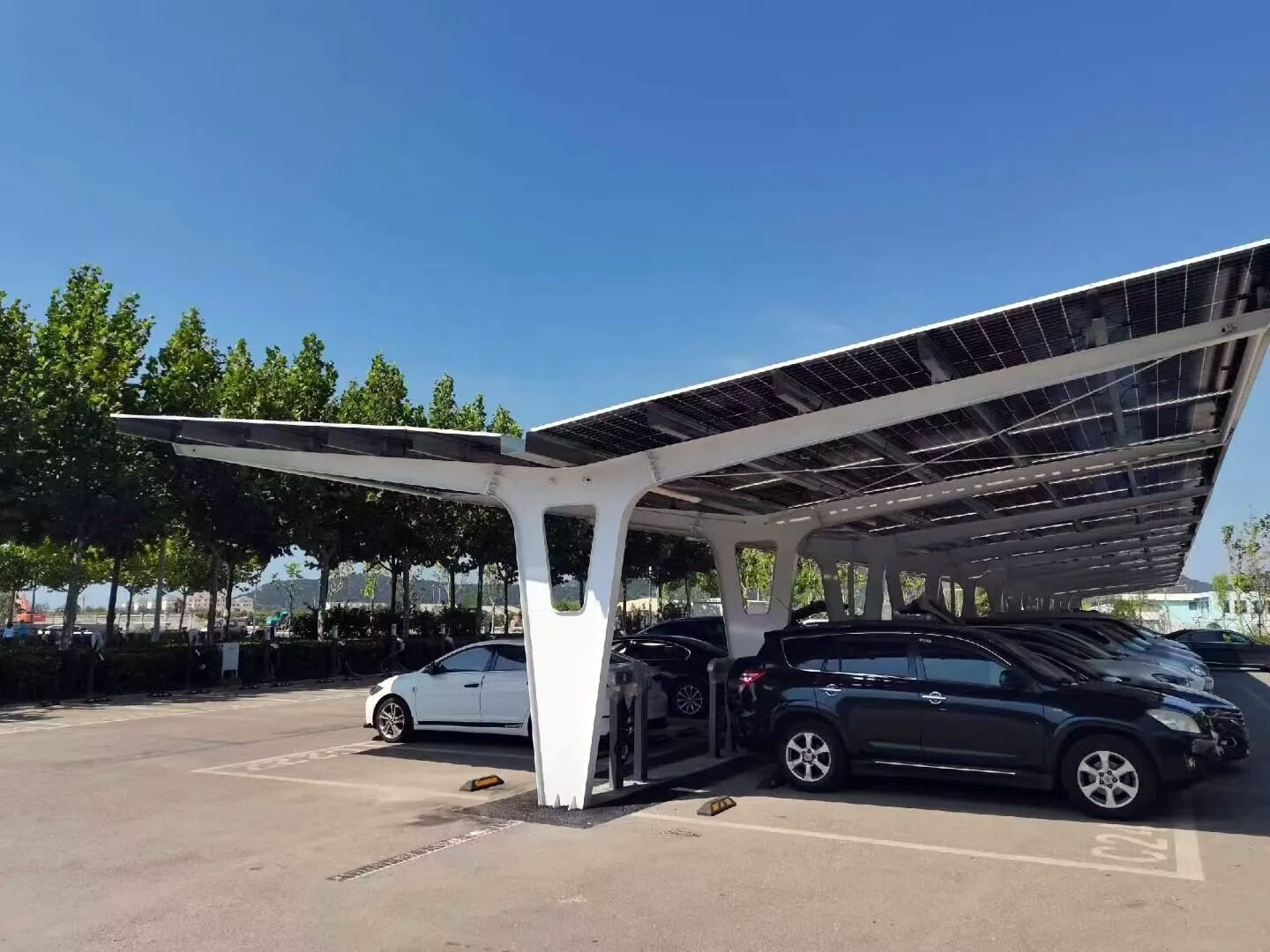
Two rows of bays on a central T-frame, the most economical layout.
US$0.070–0.100 / W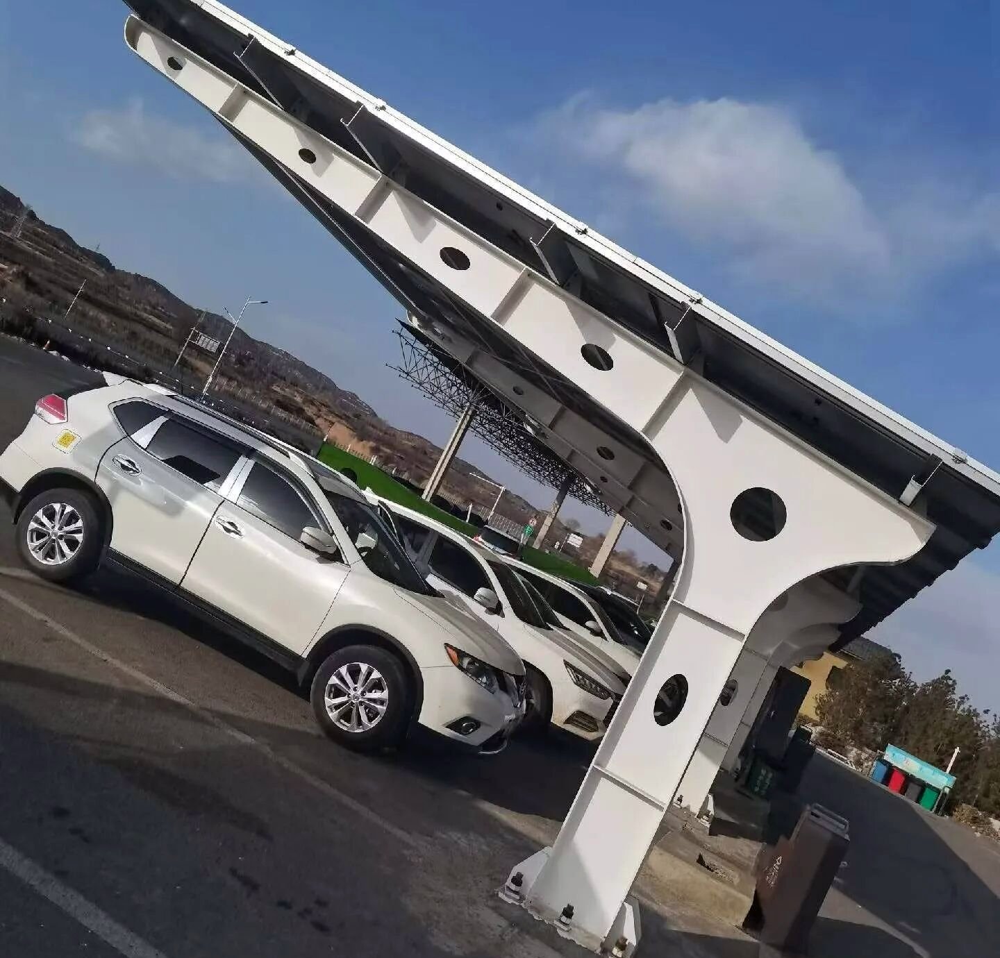
One row of bays on a single column line, open on the parking side.
US$0.075–0.110 / W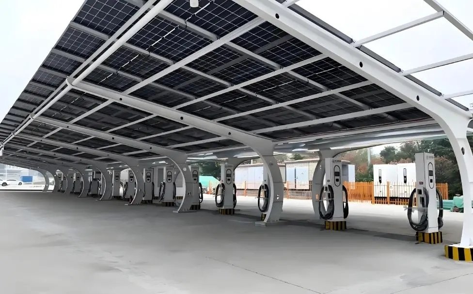
Curved tapered column for wide bays and long rows.
US$0.085–0.130 / WTell us the system, module size and quantity — most requests receive a first reply within one working day.