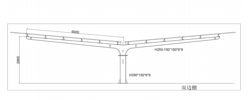
2 × 6,000 mm · 2,900 mm eave
60002900H350×150×6×8H250-150×150×6×8
Standard double-side frame with 6,000 mm each side and a 2,900 mm eave.

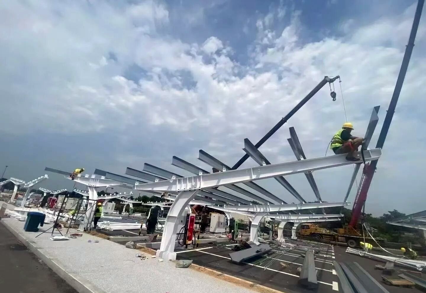
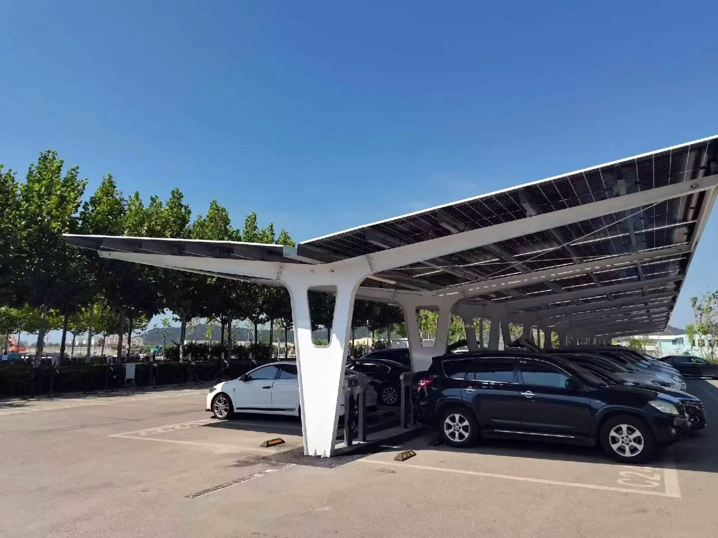 Project photograph
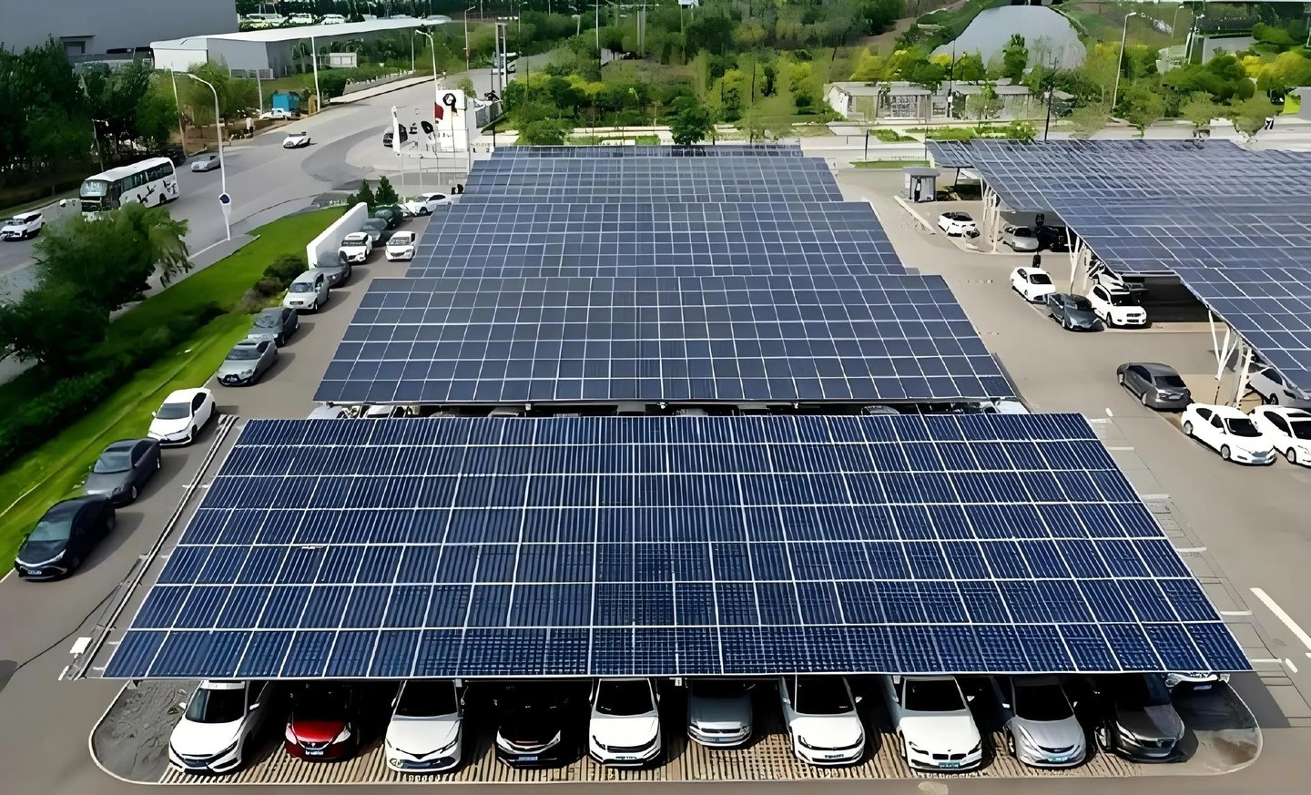
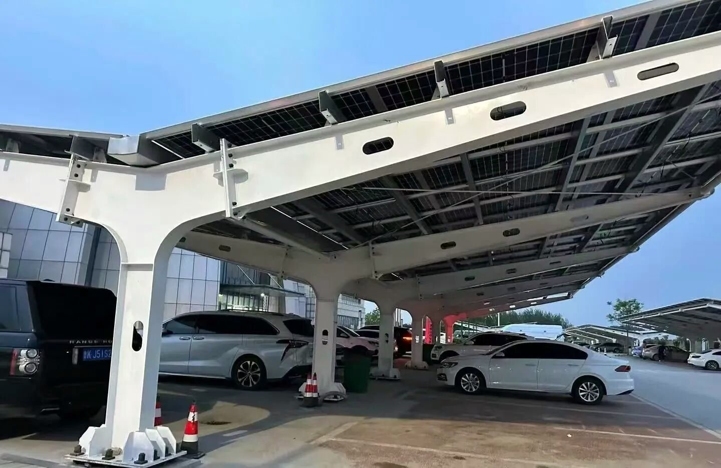
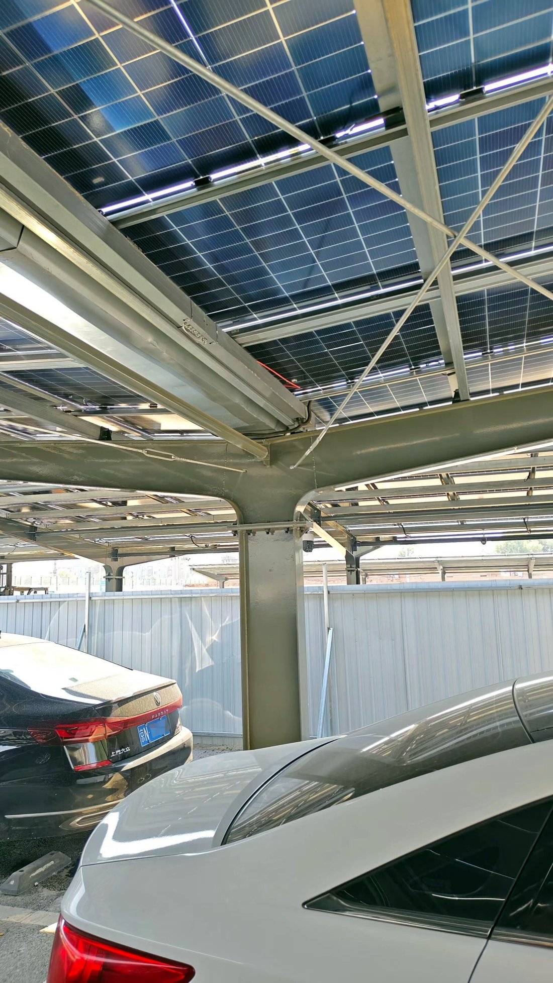
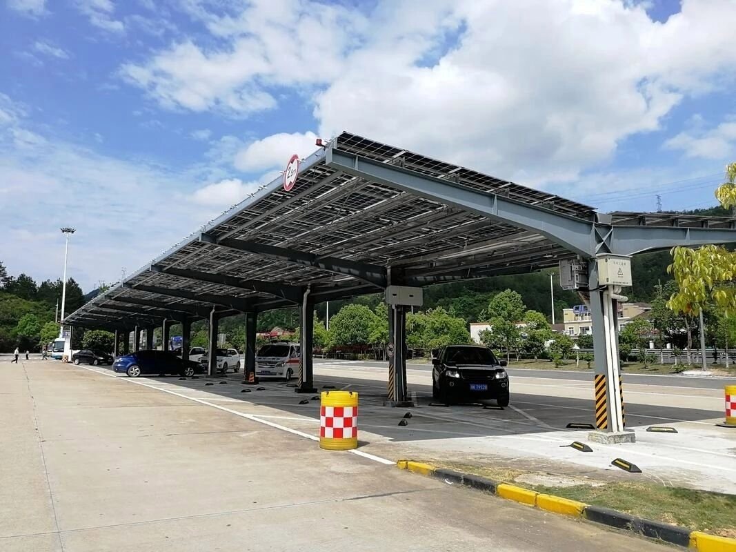
Two rows of bays on one central column line — the most economical carport layout per kW.
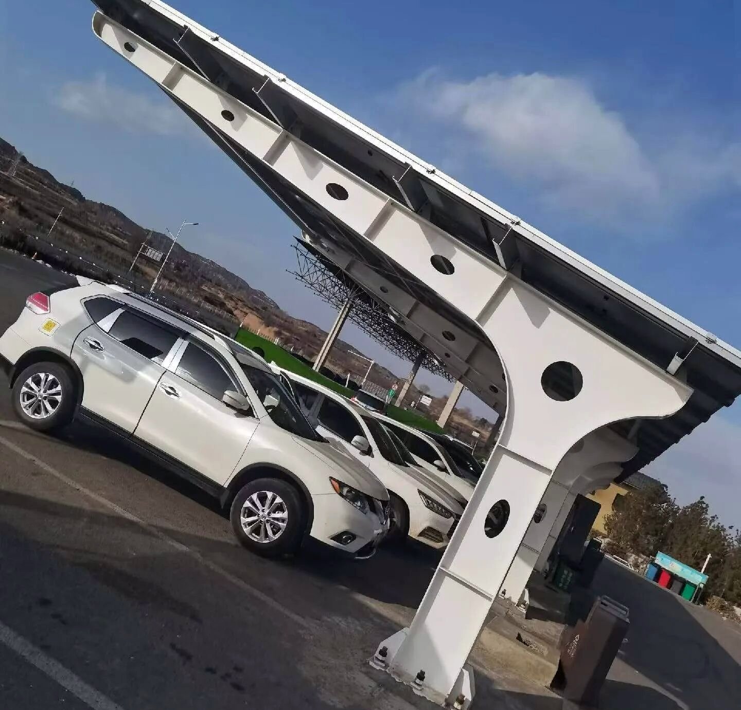
Photographs from delivered projects. Dimensions are confirmed on the approved drawing before fabrication.
A shared central column and foundation serve both parking rows.
Cut, drilled and welded first, then hot-dip galvanised; site touch-up available.
Knocked-down frames, grade 8.8 bolts, base plates set to the column grid.
Purlin spacing and clamp positions set to the module datasheet.
The double-side T-frame puts a single column line down the centre and cantilevers a rafter to each side, so one frame shelters two rows of parking bays. Because the column, base plate and foundation are shared, it is the lowest-cost layout per kW in the carport range.
Columns and rafters are fabricated from H-beam in the sections shown on the drawing, then hot-dip galvanised after cutting, drilling and welding. Purlins are set at roughly 1,600 mm to suit standard framed modules; the final module and clamping plan is confirmed before fabrication.
Typical projects are office and factory car parks, retail and logistics yards, and staff parking where two rows can run parallel to a kerb or fence line.
| Span | 2 × 6,000 mm (standard) |
|---|---|
| Eave height | 2,900 mm |
| Column | H350×150×6×8 |
| Rafter | H250-150×150×6×8 |
| Purlin spacing | ~1,600 mm |
| Foundation | Concrete pad or ground screw |
| Finish | Hot-dip galvanised or primer |
| Module fixing | Rail or direct purlin — portrait or landscape |
| Design load | Set to local wind and snow load |
| Drawing | Approved before fabrication |
Final specification is confirmed on the drawing and against the approved sample.
Photographs from carport projects — structure, underside detail and the finished parking rows.
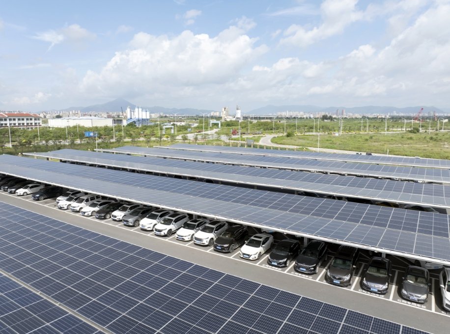
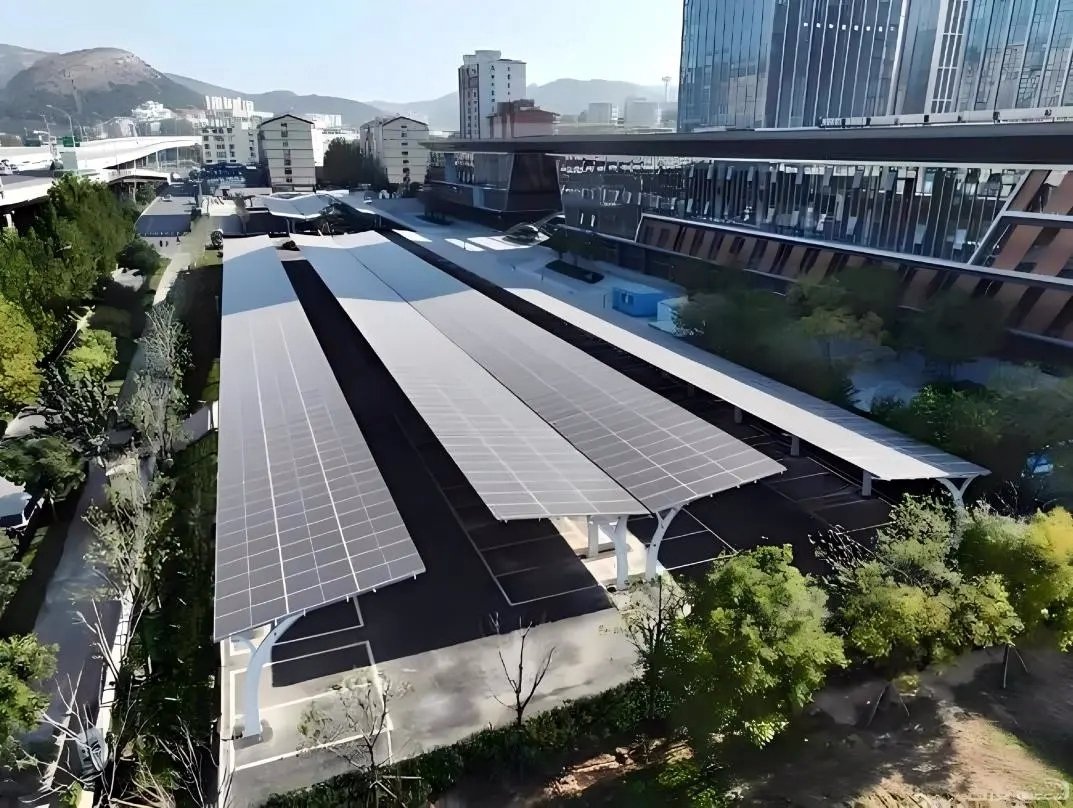
All dimensions in millimetres. Sections are engineered to the project wind and snow load; the approved drawing governs fabrication.
Standard double-side frame with 6,000 mm each side and a 2,900 mm eave.
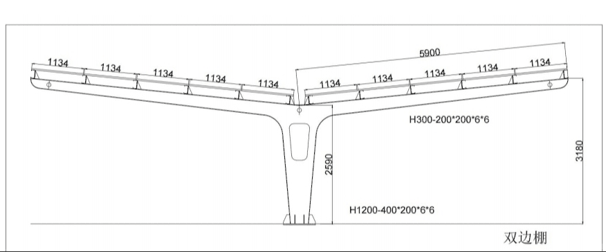
Higher ridge version with a tapered heavy column and 1,134 mm purlin spacing.
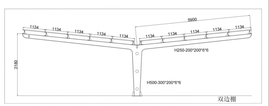
Same 5,900 mm layout with a lighter rafter and column for lower loads.
3D concepts used during layout discussion. Geometry, sections and finish are confirmed on the approved GA drawing.
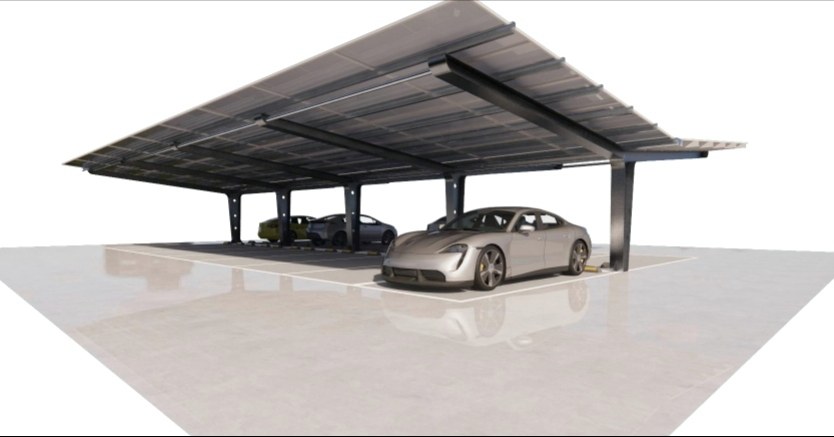
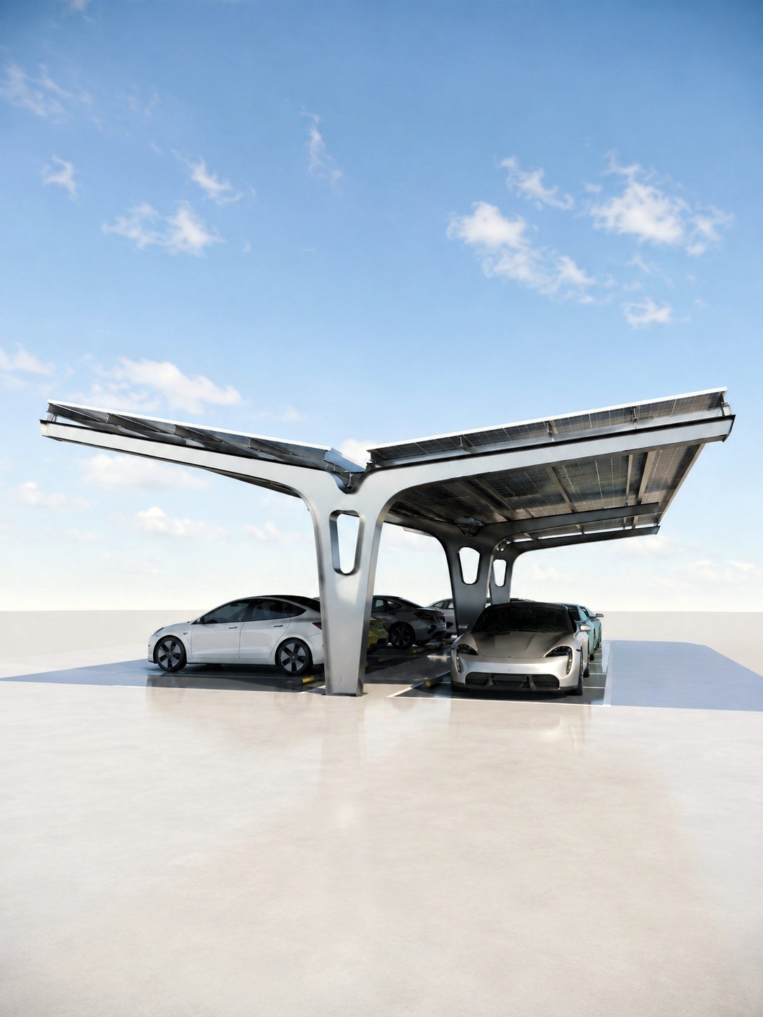
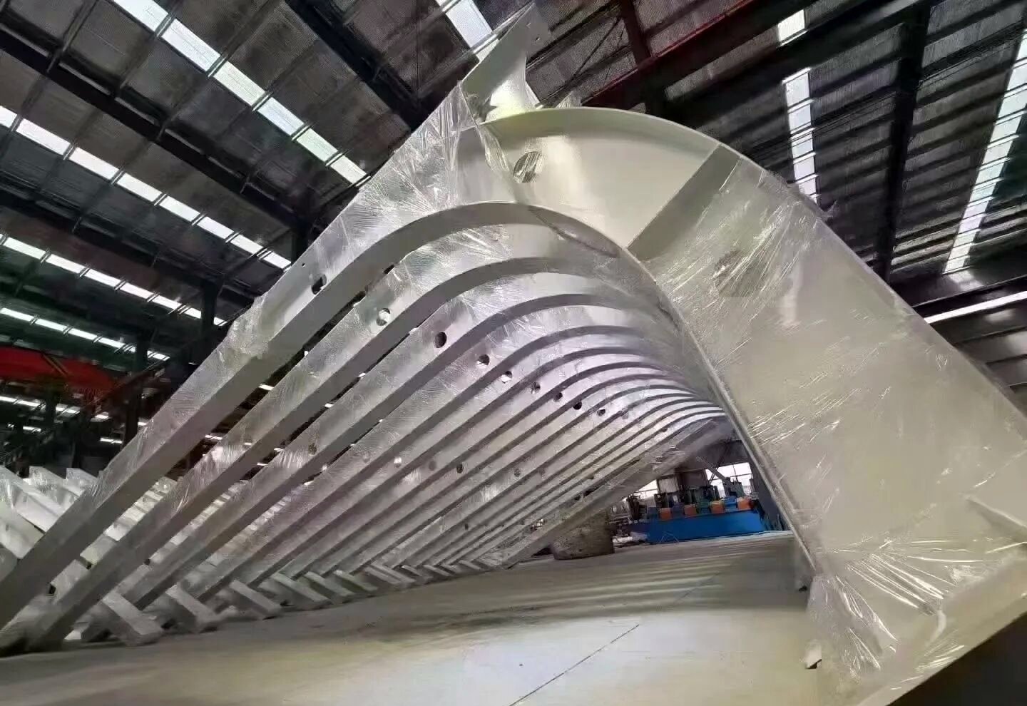
Curved and tapered frames are welded from plate, galvanised and wrapped for transport. On site the base plates are set to the column grid, frames are plumbed and bolted, then purlins and rails follow. The same crew can hand over a weather-tight canopy before modules arrive.
The frame, finish and electrical interface are set before fabrication — not adjusted on site.
Cast-in concrete pad, chemical anchor or ground screw — set out to the column base drawing.
Standard 2.5 m or 2.7 m bay; bay count and row length to the site plan.
Hot-dip galvanised to ISO 1461; primer or powder coat in a RAL colour on request.
Gutter integrated in the rafter with downpipes at agreed column positions.
Charger brackets, cable tray and meter position prepared in the frame.
LED luminaires under the purlins; fascia panels for branding.
2 × 6,000 mm from the central column, with a 2,900 mm eave. The 5,900 mm / 3,180 mm ridge versions are shown in the drawings above; other spans are engineered to the project load.
Both are used. Ground screws suit sites where soil conditions and pull-out tests allow; otherwise a cast concrete pad with anchor bolts is supplied to the base plate drawing.
Yes. Charger rails, cable tray and a riser at the column can be included — see the EV Charging Carport for the prepared version.
Bay count and site plan, module size, wind and snow load, finish, and destination port. A drawing is issued for approval before fabrication.
One row of bays on a single column line, open on the parking side.
US$0.075–0.110 / W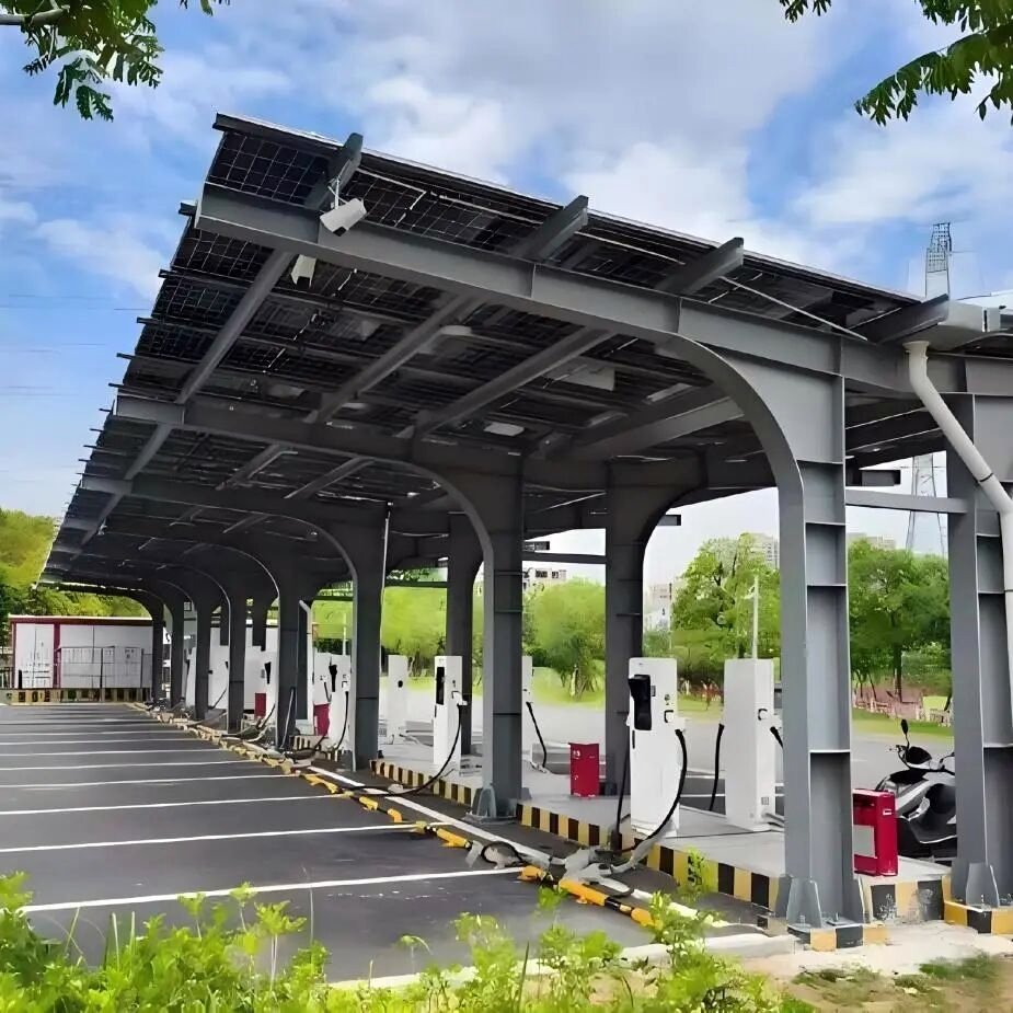
Carport structure prepared for chargers, cable tray and metering.
US$0.080–0.120 / W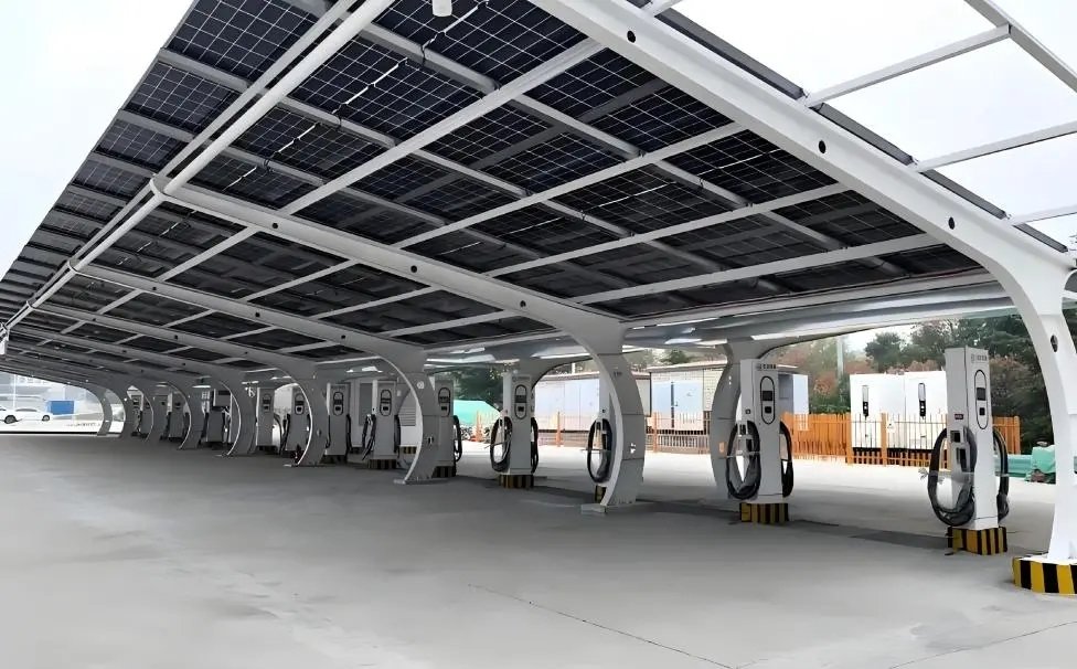
Curved tapered column for wide bays and long rows.
US$0.085–0.130 / WTell us the system, module size and quantity — most requests receive a first reply within one working day.